Paso 01· Hecho
Pull the tail lights
Cada luz trasera está sujeta por dos tornillos y un clip en la parte trasera. Sácalos completamente. Colgando de sus cables, golpean contra los guardafangos, y así es como se rompen.
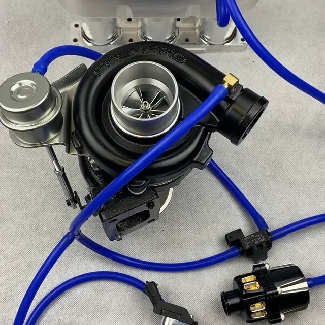
The Packard Big Turbo kit for the Can-Am Maverick X3, start to finish: teardown, coolant bypass, oil feed, the turbo, boost control, vacuum lines and the tune. Two videos from our bench, a photo on every step and the numbers that matter.
Watch it
Dos partes. Toca un capítulo y el reproductor salta a él; cada paso debajo también tiene su propio botón “ver este paso”.
Antes de empezar
Lay it all out before you start so nothing is hunted for with the turbo off.
The install
Check each one off as you go; this page remembers where you are on this device.
Las luces traseras, la fascia y la cama se quitan para que puedas alcanzar la bahía del motor.
Cada luz trasera está sujeta por dos tornillos y un clip en la parte trasera. Sácalos completamente. Colgando de sus cables, golpean contra los guardafangos, y así es como se rompen.
Cuatro tornillos Torx T30: uno en el centro, uno en el lado opuesto y dos a lo largo de la parte inferior. Con esos quitados, la fascia se quita.
On each fender, remove the five Torx T30 screws and their push-pin retainers. Now the fenders flex out far enough to reach the main bed support bolts: two per side, each with a nut on the back. With those out, lift the bed straight off.
A second set of hands keeps the bed from scraping the cage on the way off.
With the bed off you can see how much dirt lives around the turbo. Blow it out and wipe it down before you loosen a single line. Once the turbo comes off, the intake and exhaust ports are open, and anything that falls in goes into the engine.
Don’t skip this one. If you can’t get it clean, button it back up and have a shop do the swap. Dirt in an open port is how a turbo upgrade turns into an engine rebuild.
Everything that sits between you and the turbo.
Push in the reservoir’s tabs and lift it free so it’s clear of the intercooler.
Remove the two bolts on each side, then the Torx T30s. The T30s have washers, so keep track of them and don’t drop them into the bay. Two more bolts come out from inside the cab, one each side.
Lift the charge tube off its hook and unplug the intercooler fan. Loosen the charge-pipe clamps on both sides. Can-Am uses an odd size here: a 7 mm nut driver is the right tool. If your clutch cover ducting is still on, take it off too.
One thing still holds the intercooler: the electronic boost control solenoid, clipped on underneath. Most people don’t know it’s there and break it pulling the intercooler. Release its clip first. You’re installing new boost line, so the old lines can be cut.
With the charge pipes, ducting and bolts off, the intercooler lifts out. Feel around for one last hang-up before you pull.
Release the solenoid clip before you pull. This is the part that breaks.
Unhook the springs with a spring tool; they’re strong and close to your face. Remove the 13 mm bolts below. Unplug the O2 sensor at its connector, loosen the downpipe V-band clamp under its heat shield (11 mm), and pop the V-band seal loose with a pry bar.
The Packard turbo doesn’t use the factory turbo coolant lines. The bypass kit closes them off.
Find the bag marked coolant bypass kit. At the bottom of the coolant tank is a tee that feeds the turbo. Replace the tee with the straight coupler from the kit so coolant runs straight through.
The second piece is a length of heater hose with a crimped plug in one end. It’s a very tight fit on purpose. Spread the open end with pliers, warm it with a heat gun, put a drop of oil inside, then push it on.
Before you clamp it, look at the barb: there’s a bulge where it flares. Push the hose far enough past that bulge that the clamp band has a straight run of hose to bite on.
Heat and a drop of oil turn this from a fight into a thirty-second job.
The feed on top is a banjo fitting, 17 mm. It should crack loose easily. There are two copper washers; keep both. The oil drain line comes off from inside the cab.
The turbo-to-head fasteners are 10 mm and also take a Torx T40; a T40 bit on an impact makes quick work of them. Take the hardest-to-reach ones out first while you still have room. The last ones out are always the hardest when you’re also holding the turbo.
The kit’s 16-inch stainless braided feed takes its oil from the same place the factory turbo does: the oil pressure sensor, which is a banjo bolt with two copper washers.
Light torque. It takes a couple of fingers on the wrench. Break the sensor off in the case and a turbo swap becomes an engine job.
The line runs straight up, loops around and lands on top of the turbo. Shape it now, while there’s open space. A twisted line won’t sit where it needs to once the turbo is in.
Thread the kit’s M8 × 40 mm studs into the head at the exhaust flange before the turbo goes on.
The kit’s 45° −10 AN oil drain fitting goes on easiest with the turbo on the bench. Thread it on snug and angle it parallel to the bottom-corner flange bolt. Set that way, the drain line slips right on once the turbo is mounted.
Use the gasket supplied with the turbo. With the studs in, only a few threads show past the flange. Start each bottom nut by one or two threads, then inch the turbo onto the head, taking more thread as it seats, until it’s fully home. That’s the way it goes on without a fight.
Before it goes on, look into the exhaust port and the turbo inlet one last time. Anything loose in there is headed for the turbine wheel.
This is the hardest part of the job. Take your time with it.
Slide the drain line onto the 45° fitting. Before the feed goes on, prime the turbo: pour a little clean engine oil into the oil inlet on top and turn the compressor wheel by hand so the bearings aren’t dry on the first start. Then connect the braided feed.
Your new exhaust needs the room. Two ways to do it:
The bracket also held the plastic hose cover. Zip-tie the hoses to the backing piece and put the cover back on; it holds everything tight and protected.
Mount it up underneath with the connector facing the back of the vehicle. Then three barbs:
Running the full kit with the Packard plenum? The vacuum-line map below shows every line.
Reverse the teardown: intercooler and its bolts, charge pipes, fan plug and clutch ducting, then the exhaust with its springs and O2 sensor, the coolant reservoir, the bed, the fascia and the tail lights.
Flash your Packard tune before the engine runs on the new turbo; how that works is below. Check the oil level, then start it and let it idle through its first heat cycle while you look for leaks at both oil fittings, the coolant bypass plug and every vacuum line. Recheck the oil once the system has pressurized and top it off.
Watch the wideband from the first pull. We would never run a forced-induction engine without one.
Vacuum lines · full kit
Six connections on the Packard plenum kit. Tap one and its two ends light up on the photo.
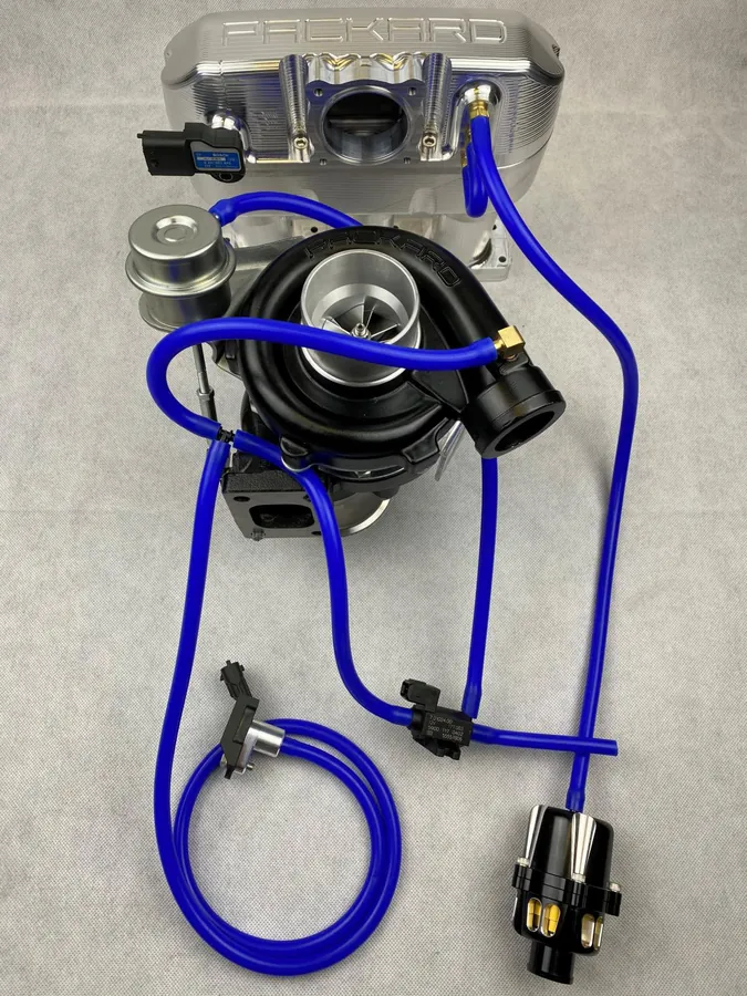
Tap a connection or a label. Lines and labels from the Packard vacuum-line instructions for the full kit with the Packard plenum.

The OEM boost sensor goes in the billet connector supplied in your kit, ahead of the throttle body.
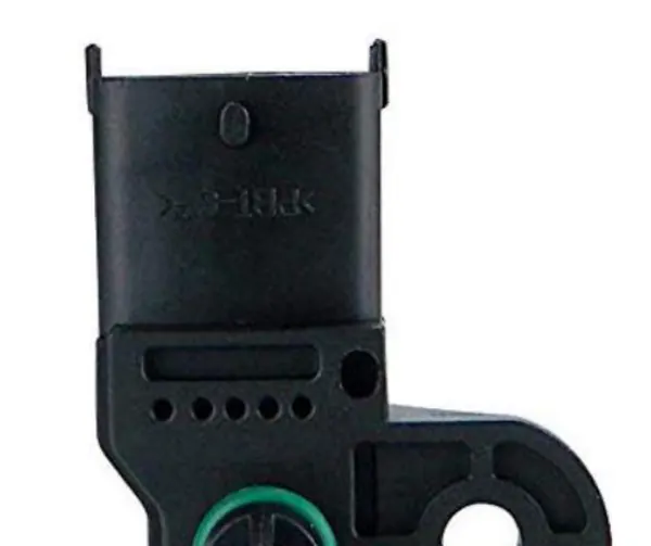
The MAP sensor goes in the plenum at port MS-1, after the throttle body. Both sensors physically fit the plenum; the one that belongs there has its connector kicking off to the left.
Flash el tune
Your Packard big turbo tune is delivered to your Dynojet Power Vision 3 by email. The short version:
Follow Dynojet’s getting-started steps in the box so the PV3 is paired to your machine.
Plug the PV3 into a computer, copy the PV_INFO file and email it to support@packardperformance.com with your mods in the subject line.
Your tune comes back by email. Its name starts with BT, for Big Turbo. Copy it onto the PV3.
PV3 on the diagnostic port in the glove box, ignition on without the brake so the engine doesn’t start, then READY TO FLASH.
Dialing it in
From the Packard kit instructions, with stock cams and the OEM boost sensor.
The Packard 2860 turbo’s wastegate comes preset to crack at 14.5 psi. If you have a hand vacuum pump such as a Mityvac, use it to confirm that baseline before you chase boost on the car.
If the car isn’t hitting the target rpm, boost or AFR, log a run on the Power Vision 3 and email it to support@packardperformance.com.
Logging steps per Dynojet’s Power Vision 3 guide for the X3.
We strongly recommend every boosted machine run a wideband AFR gauge, and we would never run a forced-induction engine without one. On this kit you’re looking for 11.5–12.5:1 at full load.
Preguntas
The Packard Big Turbo kit for the Can-Am Maverick X3, built around the Packard 2860 turbo. The vacuum-line map is for the full kit with the Packard billet plenum.
Yes. The tune is part of the system: it’s written for the big turbo and delivered to your Dynojet Power Vision 3 by email. The Power Vision 3 guide walks through it.
The Packard turbo doesn’t use the factory turbo coolant circuit. The coolant bypass kit swaps the tee at the bottom of the coolant tank for a straight coupler and plugs the turbo hose.
On the oil pressure sensor, yes: both copper washers go back on with the new feed line’s banjo, one on each side.
The boost sensor (3-pin) reads pressure before the throttle body and lives in the Packard billet connector. The MAP sensor (4-pin) reads after the throttle body and lives in the plenum. You need both.
No. BS-3 vents to atmosphere. Put a short piece of hose on it to keep dirt out and leave the end open.
11.5–12.5:1 under full load, per the Packard kit instructions.
Tell us your machine, the step number and what you’re seeing. The shop answers by email, usually the same day.
Continúa