Step 01· Done
Remove the driver’s seat
Take the driver-side seat out to expose the stock ECU.
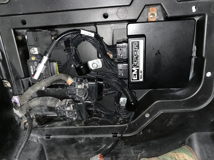
The Emtron standalone ECU goes in where the stock ECU lives, under the driver’s seat, with its ignition driver and relay beside it. Fifteen steps from our bench with a photo on every one, then the setup that keeps Smart-Lok and your gauges talking.
Before you start
The install
Check each one off as you go; this page remembers where you are on this device.
It lives under the driver’s seat.
Take the driver-side seat out to expose the stock ECU.
Remove the two 10 mm bolts that hold the ECU down.
Press the locking clip down, then pull the locking lever back. The ECU separates from the harness.
One molded tab gets cut to fit the ignition driver.
Remove the remaining clips from the molded plastic tab.
Cut the molded tab in half and remove the half closest to the center console. Make a few relief cuts with side cutters first, then trim it clean with a razor knife. This is where the ignition driver mounts.
Clean the mounting surfaces with glass cleaner, then lacquer thinner, so the Velcro and the hardware sit on bare plastic.
ECU, ignition driver and relay.
Put the double-sided Velcro tape on the Emtron ECU and mount it in the stock location, as shown.
Set the ignition driver in the space where you cut the tab. Mark its mounting holes, drill two holes through the plastic firewall, and fasten it with the supplied M6 × 16 mm Allen bolts and M6 flange nuts.
Just above the ignition driver, in the upper left corner, the relay fits right over the vertical plastic tab. Get the placement right, drill one hole for the bolt, and fasten it with an M6 × 16 mm bolt and M6 flange nut.
The adaptor harness does the work; the routing keeps it tidy.
Plug the wiring harness adaptor into the Emtron ECU, then connect the ignition driver and the relay.
Lay the harness in an “S” shape and secure it to the plastics with the wire-loom mounts.
Push the excess stock harness back into the small opening it comes through on the center console.
Plug the adaptor into the factory wiring harness. Place the two large connectors in the open space, stacked one on top of the other.
Drill three holes: one below the connectors, one between them and one on top. They anchor the zip ties.
Use the supplied zip ties through those holes to hold both large connectors down. Your install should look like this.
Last, set the data pack so the Can-Am Smart-Lok and the gauges, including the tach, keep working. The 45-second video and the menu path are below.
Smart-Lok and dash
The Emtron has to talk to the X3’s own electronics over CAN so the Smart-Lok and the gauges keep working. It’s set in Emtune, Emtron’s software.
In Emtune, open Configure, then Communications.
Go down to OEM CAN Device and choose Can-Am X3.
Select your model year by entering the number that goes with it.
Cycle through the data pack options for your machine, trying each one, until the Smart-Lok and the RPM gauge work.
Questions
In the stock location under the driver’s seat, held on with double-sided Velcro. The ignition driver and relay mount right beside it.
One thing: half of a molded plastic tab, to make room for the ignition driver. You also drill two holes for the ignition driver, one for the relay and three for the zip ties.
The data pack isn’t set for your machine yet. In Emtune, go to Configure › Communications › OEM CAN Device › Can-Am X3, pick your model year and cycle the data packs until both work.
Emtron’s Emtune, on a Windows laptop, connected to the ECU with the Ethernet tuning cable.
Yes. Keep it. Everything here reverses except the cut tab and the drilled holes.
Tell us your machine, the step number and what you’re seeing. The shop answers by email, usually the same day.